- Get link
- X
- Other Apps
The pair of bipolar transistors provides a very high current gain as compared with single standard transistor as mentioned above. The darlington pair exhibits a higher voltage between the input base and.
Calculated And Simulated Output Impedances Of The Hemt Hemt
Fmmt634 Sot23 Npn Silicon Power Darlington Transistor Datasheet

Schematic Diagram Of A C C C E Darlington Pair Unless
To illustrate how this can be done the example of an emitter follower circuit is given below.
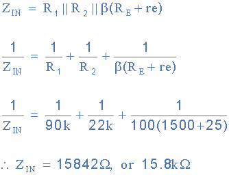
Darlington transistor impedance. In a darlington connection the input impedance of the second transistor is multiplied by the current gain of the first on. 434 which is in parallel with the input resistance of the transistor but this shunting effect can be reduced by bootstrapping. In electronics a multi transistor configuration called the darlington configuration commonly called a darlington pair is a compound structure of a particular design made by two bipolar transistors connected in such a way that the current amplified by the first transistor is amplified further by the second one.
The darlington pair can be treated as a form of transistor with the differences of the very much higher current gain and the higher base emitter voltage. The input impedance of an amplifier can be tens of ohms ohms w to a few thousand ohms kilo ohms kw for bipolar based transistor circuits up to millions of ohms mega ohms mw for fet based transistor circuits. A darlington transistor is a back to back connection of two transistors that comes as a complete package with three leads base emitter and collector as equivalent to the single transistor.
The emitter follower circuit which was just discussed lacks to meet the requirements of the circuit current gain a and the input impedance z. A commonly used compound device is known as the darlington configuration and is shown to the right a modified version of figure 816 in your text. This results in a very high overall input impedance.
In order to achieve some increase in the overall values of circuit current gain and input impedance two transistors are connected as shown in the following circuit diagram. Darlington circuit to provide improved performance and inputoutput characteristics single transistors may be combined to form compound devices. It has already been seen that the current gain from the darlington is very high.
Some of the main darlington pair characteristics and parameters are outlines below. A darlington transistor configuration also known as a darlington pair or super alpha circuit consist of two npn or pnp transistors connected together so that the emitter current of the first transistor tr1 becomes the base current of the second transistor tr2. The input impedance of the circuit is high 100kw or more being typical although this will depend to some extent on the value of the base bias resistor r1 in fig.
The output impedance of the circuit is very low typically in the region of 50w. In a darlington used as an emitter follower the output impedance of the second transistor is divided by the current gain of the second transistor.

Input Impedance Of An Amplifier And How To Calculate It

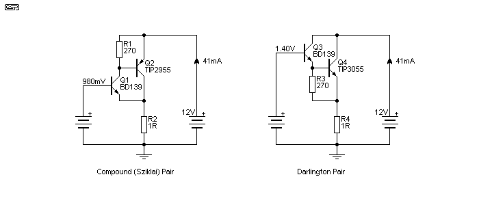
Compound Vs Darlington

Basic Circuit Building Blocks Opencircuits

Emitter Follower Darlington Amplifier Tutorialspoint

Compound Vs Darlington
How Does Input Impedance Increase Due To The Darlington

Compound Vs Darlington

Emitter Follower Darlington Amplifier Tutorialspoint

High Input Impedance Amplifier Circuits Keith

Bipolar Transistor Cookbook Part 2 Nuts Volts Magazine

Solved Use The Impedance Reflection Method For The Darlin
Darlington Circuit
- Get link
- X
- Other Apps
Comments
Post a Comment